draw 3d objects on 2d plane

Classification of some 3D projections
A 3D projection (or graphical projection) is a pattern technique used to brandish a three-dimensional (3D) object on a two-dimensional (2D) surface. These projections rely on visual perspective and aspect assay to project a complex object for viewing capability on a simpler plane. This concept of extending second geometry to 3D was mastered by Heron of Alexandria in the get-go century.[one] Heron could be called the father of 3D. 3D Project is the basis of the concept for Estimator Graphics simulating fluid flows to imitate realistic effects.[ii] Lucas Films 'ILM group is credited with introducing the concept (and even the term "Particle effect").
In 1982, the kickoff all-digital computer generated sequence for a motion picture file was in: Star Trek Ii: The Wrath of Khan. A 1984 patent related to this concept was written by William Eastward Masters, "Reckoner automatic manufacturing process and system" US4665492A using mass particles to fabricate a cup.[3] The process of particle degradation is one technology of 3D printing.
3D projections utilise the chief qualities of an object's basic shape to create a map of points, that are then continued to one another to create a visual element. The result is a graphic that contains conceptual properties to interpret that the effigy or image as non actually flat (2nd), but rather, equally a solid object (3D) existence viewed on a 2d display.
3D objects are largely displayed on two-dimensional mediums (i.e. paper and computer monitors). Every bit such, graphical projections are a commonly used design element; notably, in engineering cartoon, drafting, and figurer graphics. Projections can exist calculated through employment of mathematical analysis and formulae, or past using various geometric and optical techniques.
Overview [edit]

Several types of graphical projection compared
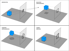
Diverse projections and how they are produced
Project is accomplished past the use of imaginary "projectors"; the projected, mental image becomes the technician's vision of the desired, finished picture.[ further caption needed ] Methods provide a uniform imaging procedure among people trained in technical graphics (mechanical drawing, figurer aided design, etc.). By following a method, the technician may produce the envisioned motion picture on a planar surface such as drawing paper.
There are two graphical projection categories, each with its ain method:
- parallel projection
- perspective projection


Parallel projection [edit]
Parallel projection corresponds to a perspective projection with a hypothetical viewpoint; i.due east. one where the camera lies an infinite distance away from the object and has an space focal length, or "zoom".
In parallel project, the lines of sight from the object to the projection plane are parallel to each other. Thus, lines that are parallel in three-dimensional space remain parallel in the two-dimensional projected image. Parallel projection also corresponds to a perspective projection with an infinite focal length (the distance from a camera's lens and focal point), or "zoom".
Images drawn in parallel projection rely upon the technique of axonometry ("to measure forth axes"), as described in Pohlke's theorem. In general, the resulting image is oblique (the rays are not perpendicular to the image plane); only in special cases the result is orthographic (the rays are perpendicular to the image airplane). Axonometry should not exist confused with axonometric projection, as in English literature the latter usually refers just to a specific class of pictorials (see beneath).
Orthographic projection [edit]
The orthographic projection is derived from the principles of descriptive geometry and is a two-dimensional representation of a three-dimensional object. It is a parallel projection (the lines of projection are parallel both in reality and in the projection plane). Information technology is the project type of pick for working drawings.
If the normal of the viewing plane (the camera direction) is parallel to one of the primary axes (which is the x, y, or z axis), the mathematical transformation is as follows; To project the 3D point , , onto the 2D signal , using an orthographic projection parallel to the y axis (where positive y represents frontward direction - contour view), the following equations can be used:


where the vector s is an arbitrary scale cistron, and c is an arbitrary offset. These constants are optional, and can be used to properly marshal the viewport. Using matrix multiplication, the equations become:

While orthographically projected images represent the three dimensional nature of the object projected, they do not represent the object as it would be recorded photographically or perceived past a viewer observing information technology direct. In particular, parallel lengths at all points in an orthographically projected prototype are of the aforementioned scale regardless of whether they are far abroad or about to the virtual viewer. As a upshot, lengths are not foreshortened equally they would be in a perspective project.
Multiview projection [edit]

Symbols used to define whether a multiview projection is either 3rd Angle (correct) or Outset Angle (left).
With multiview projections, up to six pictures (called chief views) of an object are produced, with each project plane parallel to one of the coordinate axes of the object. The views are positioned relative to each other according to either of 2 schemes: first-angle or third-angle project. In each, the appearances of views may exist thought of as being projected onto planes that form a 6-sided box effectually the object. Although six unlike sides tin exist drawn, normally three views of a drawing give plenty information to brand a 3D object. These views are known equally front view, summit view, and stop view. The terms elevation, programme and department are too used.
Oblique projection [edit]

Potting demote drawn in cabinet projection with an bending of 45° and a ratio of 2/three

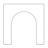
Stone arch drawn in armed services perspective
In oblique projections the parallel projection rays are non perpendicular to the viewing plane as with orthographic projection, just strike the projection plane at an angle other than ninety degrees. In both orthographic and oblique projection, parallel lines in space appear parallel on the projected image. Because of its simplicity, oblique projection is used exclusively for pictorial purposes rather than for formal, working drawings. In an oblique pictorial drawing, the displayed angles among the axes also as the foreshortening factors (scale) are arbitrary. The distortion created thereby is normally adulterate past aligning ane plane of the imaged object to be parallel with the plane of project thereby creating a true shape, full-size image of the chosen plane. Special types of oblique projections are:
Cavalier projection (45°) [edit]
In condescending project (sometimes cavalier perspective or high view point) a point of the object is represented by three coordinates, x, y and z. On the drawing, it is represented by just two coordinates, x″ and y″. On the flat cartoon, two axes, x and z on the figure, are perpendicular and the length on these axes are drawn with a one:1 scale; it is thus similar to the dimetric projections, although it is not an axonometric project, as the third axis, here y, is drawn in diagonal, making an arbitrary angle with the x″ centrality, usually 30 or 45°. The length of the tertiary centrality is non scaled.
Cabinet project [edit]
The term chiffonier project (sometimes cabinet perspective) stems from its use in illustrations by the article of furniture industry.[ citation needed ] Like cavalier perspective, one confront of the projected object is parallel to the viewing airplane, and the tertiary centrality is projected every bit going off in an angle (typically 30° or 45° or arctan(2) = 63.4°). Different cavalier projection, where the third axis keeps its length, with cabinet projection the length of the receding lines is cut in half.
Military projection [edit]
A variant of oblique projection is called military project. In this example, the horizontal sections are isometrically drawn and then that the floor plans are not distorted and the verticals are fatigued at an angle. The military project is given by rotation in the xy-plane and a vertical translation an amount z.[4]
Axonometric projection [edit]

Axonometric projections bear witness an image of an object as viewed from a skew direction in order to reveal all iii directions (axes) of space in one picture.[five] Axonometric projections may be either orthographic or oblique. Axonometric instrument drawings are often used to gauge graphical perspective projections, but there is attendant distortion in the approximation. Considering pictorial projections innately incorporate this distortion, in musical instrument drawings of pictorials keen liberties may then be taken for economic system of try and best effect.[ clarification needed ]
Axonometric project is farther subdivided into three categories: isometric projection, dimetric projection, and trimetric projection, depending on the exact angle at which the view deviates from the orthogonal.[6] [7] A typical characteristic of orthographic pictorials is that one axis of space is usually displayed as vertical.
Axonometric projections are also sometimes known as auxiliary views, as opposed to the primary views of multiview projections.
Isometric projection [edit]
In isometric pictorials (for methods, run across Isometric projection), the direction of viewing is such that the three axes of space announced every bit foreshortened, and there is a common angle of 120° between them. The distortion acquired by foreshortening is compatible, therefore the proportionality of all sides and lengths are preserved, and the axes share a mutual calibration. This enables measurements to be read or taken directly from the drawing.
Dimetric projection [edit]
In dimetric pictorials (for methods, run across Dimetric projection), the direction of viewing is such that two of the three axes of space appear equally foreshortened, of which the attendant calibration and angles of presentation are determined co-ordinate to the bending of viewing; the scale of the third management (vertical) is determined separately. Approximations are mutual in dimetric drawings.
Trimetric projection [edit]
In trimetric pictorials (for methods, run across Trimetric project), the direction of viewing is such that all of the three axes of space appear unequally foreshortened. The scale forth each of the 3 axes and the angles amongst them are determined separately as dictated past the angle of viewing. Approximations in Trimetric drawings are mutual.
Limitations of parallel projection [edit]

An instance of the limitations of isometric projection. The height difference betwixt the red and blue balls cannot be determined locally.

The Penrose stairs depicts a staircase which seems to arise (anticlockwise) or descend (clockwise) yet forms a continuous loop.
Objects fatigued with parallel projection exercise not appear larger or smaller as they extend closer to or abroad from the viewer. While advantageous for architectural drawings, where measurements must be taken directly from the image, the event is a perceived baloney, since different perspective projection, this is not how our optics or photography commonly work. It too can easily result in situations where depth and distance are difficult to judge, as is shown in the analogy to the correct.
In this isometric drawing, the blue sphere is ii units college than the red i. Still, this difference in summit is non apparent if one covers the right half of the picture show, as the boxes (which serve as clues suggesting height) are then obscured.
This visual ambiguity has been exploited in op art, as well as "incommunicable object" drawings. M. C. Escher's Waterfall (1961), while not strictly utilizing parallel projection, is a well-known example, in which a channel of water seems to travel unaided along a downward path, only to then paradoxically autumn in one case over again as it returns to its source. The water thus appears to disobey the law of conservation of energy. An extreme example is depicted in the moving picture Inception, where by a forced perspective trick an immobile stairway changes its connectivity. The video game Fez uses tricks of perspective to determine where a thespian tin and cannot motility in a puzzle-similar mode.
Perspective project [edit]

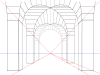
Perspective of a geometric solid using two vanishing points. In this case, the map of the solid (orthogonal projection) is fatigued beneath the perspective, as if bending the ground plane.

Axonometric projection of a scheme displaying the relevant elements of a vertical flick aeroplane perspective. The continuing point (P.S.) is located on the basis aeroplane π, and the point of view (P.Five.) is right above it. P.P. is its projection on the pic plane α. Fifty.O. and 50.T. are the horizon and the ground lines (linea d'orizzonte and linea di terra). The bold lines south and q prevarication on π, and intercept α at Ts and Tq respectively. The parallel lines through P.Five. (in red) intercept L.O. in the vanishing points Fs and Fq: thus one tin can draw the projections s′ and q′, and hence also their intersection R′ on R.
Perspective project or perspective transformation is a linear project where three dimensional objects are projected on a picture plane. This has the outcome that distant objects appear smaller than nearer objects.
Information technology too means that lines which are parallel in nature (that is, meet at the bespeak at infinity) appear to intersect in the projected image, for example if railways are pictured with perspective projection, they appear to converge towards a single signal, called the vanishing betoken. Photographic lenses and the human eye work in the same mode, therefore perspective projection looks near realistic.[eight] Perspective projection is usually categorized into 1-point, two-indicate and three-betoken perspective, depending on the orientation of the projection plane towards the axes of the depicted object.[ix]
Graphical projection methods rely on the duality between lines and points, whereby two straight lines determine a point while two points decide a straight line. The orthogonal projection of the middle bespeak onto the moving-picture show plane is chosen the master vanishing point (P.P. in the scheme on the left, from the Italian term punto principale, coined during the renaissance).[10]
Two relevant points of a line are:
- its intersection with the moving-picture show plane, and
- its vanishing signal, plant at the intersection between the parallel line from the centre indicate and the picture airplane.
The principal vanishing betoken is the vanishing point of all horizontal lines perpendicular to the picture aeroplane. The vanishing points of all horizontal lines lie on the horizon line. If, as is often the case, the moving-picture show plane is vertical, all vertical lines are fatigued vertically, and have no finite vanishing point on the motion picture plane. Diverse graphical methods can be easily envisaged for projecting geometrical scenes. For example, lines traced from the eye point at 45° to the movie plane intersect the latter along a circle whose radius is the distance of the eye point from the aeroplane, thus tracing that circle aids the construction of all the vanishing points of 45° lines; in item, the intersection of that circle with the horizon line consists of two altitude points. They are useful for drawing chessboard floors which, in plow, serve for locating the base of objects on the scene. In the perspective of a geometric solid on the right, after choosing the primary vanishing point —which determines the horizon line— the 45° vanishing point on the left side of the drawing completes the characterization of the (equally distant) point of view. Two lines are drawn from the orthogonal project of each vertex, one at 45° and one at 90° to the moving picture aeroplane. After intersecting the ground line, those lines go toward the distance point (for 45°) or the master bespeak (for ninety°). Their new intersection locates the projection of the map. Natural heights are measured above the ground line so projected in the same way until they meet the vertical from the map.
While orthographic projection ignores perspective to allow accurate measurements, perspective project shows distant objects every bit smaller to provide additional realism.
Mathematical formula [edit]
The perspective projection requires a more involved definition every bit compared to orthographic projections. A conceptual aid to understanding the mechanics of this projection is to imagine the second projection equally though the object(s) are being viewed through a photographic camera viewfinder. The camera's position, orientation, and field of view control the behavior of the project transformation. The following variables are defined to draw this transformation:
- – the 3D position of a bespeak A that is to exist projected.
- – the 3D position of a point C representing the camera.
- – The orientation of the photographic camera (represented by Tait–Bryan angles).
- – the display surface's position relative to the photographic camera pinhole C.[xi]


Near conventions use positive z values (the plane being in front of the pinhole), even so negative z values are physically more correct, but the image will exist inverted both horizontally and vertically. Which results in:
When and the 3D vector is projected to the 2D vector .


Otherwise, to compute nosotros outset ascertain a vector as the position of bespeak A with respect to a coordinate organisation defined by the camera, with origin in C and rotated by with respect to the initial coordinate system. This is achieved by subtracting from so applying a rotation past to the result. This transformation is often called a camera transform , and tin be expressed equally follows, expressing the rotation in terms of rotations about the x, y, and z axes (these calculations presume that the axes are ordered as a left-handed system of axes): [12] [13]


This representation corresponds to rotating by three Euler angles (more properly, Tait–Bryan angles), using the xyz convention, which can be interpreted either equally "rotate nearly the extrinsic axes (axes of the scene) in the order z, y, ten (reading right-to-left)" or "rotate about the intrinsic axes (axes of the camera) in the social club ten, y, z (reading left-to-correct)". Annotation that if the camera is not rotated ( ), then the matrices drop out (as identities), and this reduces to but a shift:


Alternatively, without using matrices (let united states of america supercede with and so on, and abbreviate to and to ):


This transformed point can then be projected onto the 2nd plane using the formula (here, 10/y is used as the projection plane; literature likewise may use x/z):[14]
![{\displaystyle {\begin{aligned}\mathbf {b} _{x}&={\frac {\mathbf {e} _{z}}{\mathbf {d} _{z}}}\mathbf {d} _{x}+\mathbf {e} _{x},\\[5pt]\mathbf {b} _{y}&={\frac {\mathbf {e} _{z}}{\mathbf {d} _{z}}}\mathbf {d} _{y}+\mathbf {e} _{y}.\end{aligned}}}](https://wikimedia.org/api/rest_v1/media/math/render/svg/f002d3d4ed5e51f66a9e80bad596258adb82ed25)
Or, in matrix class using homogeneous coordinates, the organization

in conjunction with an argument using similar triangles, leads to partition by the homogeneous coordinate, giving

The distance of the viewer from the brandish surface, , directly relates to the field of view, where is the viewed angle. (Notation: This assumes that you map the points (-one,-1) and (1,ane) to the corners of your viewing surface)


The above equations can also be rewritten as:

In which is the display size, is the recording surface size (CCD or film), is the altitude from the recording surface to the archway student (camera middle), and is the distance, from the 3D point being projected, to the entrance pupil.


Subsequent clipping and scaling operations may be necessary to map the 2D plane onto any item display media.
Weak perspective projection [edit]
A "weak" perspective projection uses the same principles of an orthographic projection, but requires the scaling gene to be specified, thus ensuring that closer objects appear bigger in the project, and vice versa. It tin exist seen as a hybrid between an orthographic and a perspective projection, and described either as a perspective projection with individual betoken depths replaced by an average abiding depth ,[15] or simply equally an orthographic projection plus a scaling.[16]


The weak-perspective model thus approximates perspective projection while using a simpler model, similar to the pure (unscaled) orthographic perspective. It is a reasonable approximation when the depth of the object along the line of sight is pocket-sized compared to the distance from the camera, and the field of view is small. With these conditions, it tin can be assumed that all points on a 3D object are at the aforementioned distance from the camera without significant errors in the projection (compared to the full perspective model).
Equation
![{\displaystyle {\begin{aligned}&P_{x}={\frac {X}{Z_{\text{ave}}}}\\[5pt]&P_{y}={\frac {Y}{Z_{\text{ave}}}}\end{aligned}}}](https://wikimedia.org/api/rest_v1/media/math/render/svg/0d66248cfb79bcde6f7e7d136e18c3a7498b4ddd)
assuming focal length .

Diagram [edit]
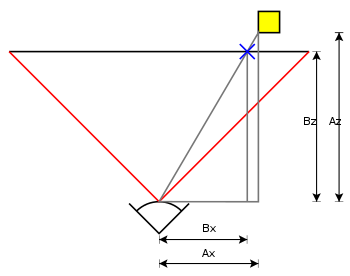
To make up one's mind which screen x-coordinate corresponds to a point at multiply the bespeak coordinates past:


where
- is the screen x coordinate
- is the model x coordinate
- is the focal length—the axial distance from the camera center to the prototype plane
- is the subject distance.


Because the camera is in 3D, the same works for the screen y-coordinate, substituting y for x in the above diagram and equation.
You can use that to do clipping techniques, replacing the variables with values of the point that'due south are out of the FOV-bending and the betoken inside Camera Matrix.
This technique, too known as "Inverse Camera", is a Perspective Projection Calculus with known values to summate the final point on visible angle, projecting from the invisible point, after all needed transformations finished.
Run across also [edit]
- 3D computer graphics
- Camera matrix
- Computer graphics
- Cross section (geometry)
- Cross-sectional view
- Curvilinear perspective
- Cutaway drawing
- Descriptive geometry
- Engineering drawing
- Exploded-view drawing
- Homogeneous coordinates
- Homography
- Map projection (including Cylindrical project)
- Multiview projection
- Perspective (graphical)
- Program (drawing)
- Technical drawing
- Texture mapping
- Transform, clipping, and lighting
- Video card
- Viewing frustum
- Virtual world
References [edit]
- ^ Peddie, Jon. (2013). The history of visual magic in computers : how beautiful images are made in CAD, 3D, VR and AR. London: Springer. p. 25. ISBN978-i-4471-4932-3. OCLC 849634980.
- ^ Peddie, Jon. (2013). The history of visual magic in computers : how beautiful images are made in CAD, 3D, VR and AR. London: Springer. pp. 67–69. ISBN978-1-4471-4932-iii. OCLC 849634980.
- ^ Patent 4665492, Figure 2A, 2B and 2C.
- ^ "Axonometric projections - a technical overview". Retrieved 24 April 2015.
- ^ Mitchell, William; Malcolm McCullough (1994). Digital pattern media. John Wiley and Sons. p. 169. ISBN978-0-471-28666-0.
- ^ Maynard, Patric (2005). Drawing distinctions: the varieties of graphic expression. Cornell University Press. p. 22. ISBN978-0-8014-7280-0.
- ^ McReynolds, Tom; David Blythe (2005). Advanced graphics programming using openGL. Elsevier. p. 502. ISBN978-1-55860-659-3.
- ^ D. Hearn, & Grand. Baker (1997). Reckoner Graphics, C Version. Englewood Cliffs: Prentice Hall], chapter 9
- ^ James Foley (1997). Computer Graphics. Boston: Addison-Wesley. ISBN 0-201-84840-half-dozen], chapter 6
- ^ Kirsti Andersen (2007), The geometry of an fine art, Springer, p. xxix, ISBN9780387259611
- ^ Ingrid Carlbom, Joseph Paciorek (1978). "Planar Geometric Projections and Viewing Transformations" (PDF). ACM Computing Surveys. x (4): 465–502. CiteSeerXten.1.i.532.4774. doi:10.1145/356744.356750. S2CID 708008.
- ^ Riley, 1000 F (2006). Mathematical Methods for Physics and Technology . Cambridge University Printing. pp. 931, 942. doi:10.2277/0521679710. ISBN978-0-521-67971-8.
- ^ Goldstein, Herbert (1980). Classical Mechanics (2d ed.). Reading, Mass.: Addison-Wesley Pub. Co. pp. 146–148. ISBN978-0-201-02918-5.
- ^ Sonka, M; Hlavac, V; Boyle, R (1995). Paradigm Processing, Analysis & Machine Vision (2nd ed.). Chapman and Hall. p. xiv. ISBN978-0-412-45570-iv.
- ^ Subhashis Banerjee (2002-02-xviii). "The Weak-Perspective Photographic camera".
- ^ Change, T. D. (July 1992). 3D Pose from 3 Corresponding Points nether Weak-Perspective Projection (PDF) (Technical report). MIT AI Lab.
Further reading [edit]
- Kenneth C. Finney (2004). 3D Game Programming All in One . Thomson Course. p. 93. ISBN978-1-59200-136-i.
3D projection.
- Koehler; Dr. Ralph (December 2000). second/3D Graphics and Splines with Source Code. ISBN978-0759611870.
External links [edit]
- Creating 3D Environments from Digital Photographs
choatebroateretted.blogspot.com
Source: https://en.wikipedia.org/wiki/3D_projection
0 Response to "draw 3d objects on 2d plane"
Post a Comment